
A few months ago, I had an interview for a co-op for robotics and to my surprise got a call back with an offer. The place is a decent way away by car, but there is a train if I could bike to the stations. I wanted to get some practice in designing a complete prototype before starting the co-op, so I wanted to challenge myself. I’ve wanted to make an autonomous bike I could ride into work on and then have itself go park, and now I’ve been given the opportunity.
This post covers the progress I made on that bike.

The Beginning
My first goal was this should be as cheap as possible, using as many parts that I already own. I decided I was going to have an old hoverboard motor drive the back wheel, find a strong enough servo to drive the steering with a belt and pulley, and use the robotic actuator that I have been prototyping for a reaction wheel to balance the bike.
Choosing Parts and Prototyping Steering
I originally started with a cheap, but new, bike that was available to me. It wasn’t my favorite since the frame had a curve to it that would be hard to model around, but I just decided to try anyway. I found a servo on Amazon that had what I estimated to have enough torque to drive the steering and began to draft a simple mount I could 3D print with Creo Parametric. A secondary goal I had with this project was to learn the software I would be using for my co-op. I made a very simple mount that broke because I forgot about the brake line. I zip tied the mount on enough to get this clip.
I redesigned the mount to account for the brake line and it actually fit decently well, but the 3D print quality from my Ender 3 was not tuned enough for this and delaminated between the layers.

The mount redesigned in Creo. I have been a SolidWorks user for several years, and learning Creo has been… fun. I do see the benefits in using it now, and may switch to it once I am more comfortable.

Around this time, I also found a bike on the side of the road that fit this project so much better! I got very lucky. The frame was completely aluminum and even some carbon fiber making it very light but rigid. It even fit the mount I had already printed quite well.

I wanted to get the steering working just enough to start working on the electronics though, and I did not work want begin the continuous project that is my Ender 3. I decided to try making the servo mount from parts from my CNC router and aluminum extrusion.
My idea for the mount was that I would cut the profile of the aluminum tube of the frame into blocks of MDF that could clamp between two bars of aluminum and from that I could mount the servo.

The block for the MDF cut on the router. I exported the face of this part to a DXF from Creo to Carbide Create to generate the G-code for my Shapeoko 3 router.

Two of the MDF blocks fitted for the pipe, two threaded rods are fed through the top and bottom of the aluminum extrusion as you can see here.

Prototyping the Drive


To move the bike, I opted to friction drive the back wheel with my old hoverboard motor. I mounted an aluminum frame to the back of the bike similar to how those basket mounts are held in place. I don’t have a lathe or anything, so I needed a simple way to mount the hoverboard motor to the frame. I tried with a simple PLA clamp, but I knew that wouldn’t hold.

For this to actually work, the PLA part would need to be stronger. Much stronger. Luckily, my friend interning at MarkForged offered to print parts for me out of their Carbon Fiber Nylon filament (Onyx). They use continuous fiber in their printing which helps make this part crazy strong. I’ve ridden several miles now with the mount, and it has not broken.
This honestly worked way better than I thought. With a larger battery, and a beefier ESC, this makes a decent DIY e-bike.
The Self-Balancing Reaction Wheel
This part I knew would be the hardest. I wanted to balance the bike with a reaction wheel as an inverted pendulum. I have been working on an actuator that would be perfect for this reaction wheel. My prototype for it consisted of the laser cut cycloidal drive, and I needed to get it to a working point with the motor and driver I had on hand. The driver being the SimpleFOC board.
It took a lot of troubleshooting and messing with the control script and SimpleFOC to get this actuator working. I eventually got angle control working after figuring out what to do with my PID parameters.
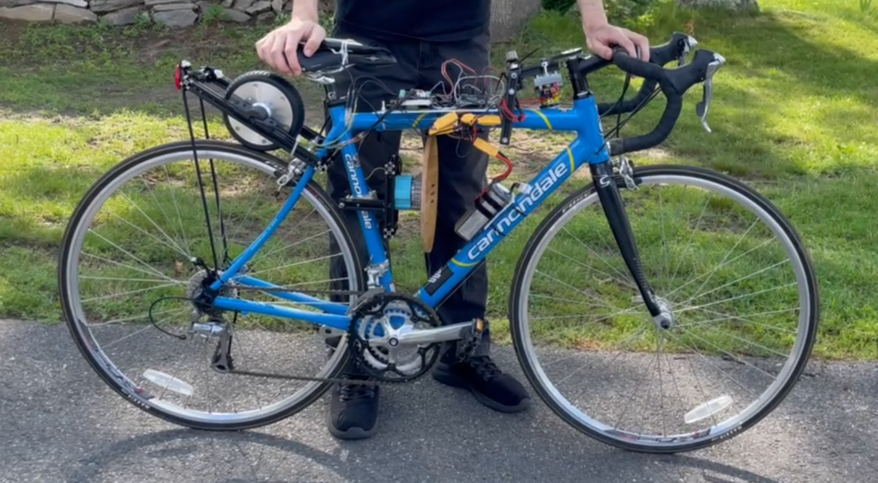
Very Rough Semi-Functional Prototype
I mounted the actuator and reaction wheel to the bike in a similar way to the mount I made for the steering with the MDF blocks and aluminum extrusion clamps.
With everything mounted on the bike, I noticed that it was very top heavy and this would mean the reaction wheel made of wood probably does not have enough mass to create sufficient torque.
I began working on a simple control script though to begin learning how to control the actuator in reaction to an IMU’s data output.
Here is the actuator controlling its velocity based on the tilt angle of the bike. It’s a simple proportional function and was solely to practice getting the IMU data and controlling the actuator with it via SimpleFOC velocity control.
I wanted this bike to be able to be controlled via ROS 2 in the future. As a quick demo though, I created a simple web application hosted on the Jetson Nano on the bike with a joystick. The side to side joystick movements control the servo via an Arduino connected over serial to the Jetson. The up and down movements control the speed of the hoverboard motor with the ESC connected with PWM to the Arduino.
What’s Next?
My next steps with this bike is to
- Redesign it for stronger 3D printed parts.
- Utilize V2 of my Minerva Actuator.
- Get laser cut steel for a beefier reaction wheel.
- Create a proper enclosure for the electronics.
And most importantly,
- Learn how to develop a control algorithm to balance the bike.
I’ve found a few resources and academic papers on this topic. I am going to begin by exploring Simulink in Matlab, and doing more research on PID tuning and motor control.
Sneak Preview – Minerva Actuator V2
The actuator I am going to use for the reaction wheel I have redesigned and had printed out of carbon fiber. The entire package without the motor driver currently is under $100 (including the cost of fiber filament by weight.) I will be conducting torque and speed tests on this actuator before trying to implement it on the revision of the bike.
Reply